
E34 M5 HID LOW BEAM INSTALL
How To Eliminate the "LOW BEAM" Diagnostic Message From the OBC of
E34 and E32 cars.
By Dave
McLaren
with special thanks to Garrick Louie, who shared with me his relay setup
devised for his E34 M5
Information herein may also be applicable to other models, but
I can't be sure of this. I am hearing conflicting information from E36 owners
about how the LKM / OBC checks the low beam bulbs. I trying to find out more
information, to help determine if this solution will help some E36 owners. One
thing I do know is that Garrick Louie installed the same Philips HID system
on his '98 M3 and did not need any relay setup. He had no problem with the "low
beam" message, even though his low beam leads were connected directly to
the Philips ballasts. However, at least one other E36 owner told me that when
he connected the low beam leads directly to the Philips ballasts, his OBC displayed
"low beam" when he turned on the headlights and not before.
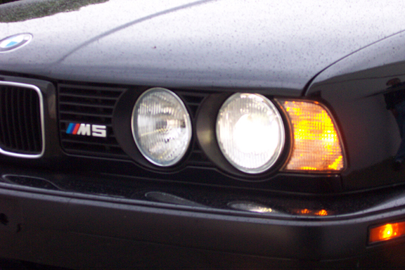
I have been using my HID low beams for two weeks since installing this fix,
and there are no problems.
This page covers my experience installing an HID
kit into my E34 M5, particularly the problem of the On Board Computer (OBC)
displaying a "low beam" failure message despite the fact that the
HID low beams were functioning fine. Please maximize your browser screen to
make this page easier to view. I'm not a web guy, and doing this made it easier
to view on my monitor.
USELESS WIRING HARNESS & RELAYS SUPPLIED WITH HID KIT
I bought the HID kit from a seller on eBay, new in box, though there was no
brand name on the box. The seller said he'd bought several sets from a car accessory
shop gone out of business, and he was kind enough to deliver it to me in person
since he wasn't far away. The kit included genuine Philips ballasts and bulbs,
and also a wiring harness with it's own 12 volt power leads, relays and 15 amp
fuses. The wiring harness was not manufactured by Philips, but by a manufacturer
unknown to the seller. The car's low beam female leads would plug into the harness'
male connectors, and the harness had female plugs of the same style as the factory
plugs that would connect to the HID ballasts. The harness included two independently
fused 12Volt N/O (normally open) relays, which would be triggered by the 12
volt current when the lights are turned one, thereby switching the relay to
the CLOSED position and causing power from the separate 12 Volt leads, described
below, to flow to the HID ballasts.
The + power lead had been attached to the terminal below the + jump start access
terminal under the hood. Since the battery on the M5 is under the rear seat,
BMW provided this beefy terminal for a jumper cable. Two main + leads are connected
beneath the jump start access terminal, one lead coming from the alternator,
the other lead going to the battery. The + lead of the kit actually had two
red hot wires attached to it, with each hot wire going to its own relay. One
hot lead and relay for each low beam. The - lead for the kit was properly grounded
to the body, on the inside of the fender well, in front of the strut tower on
the driver side.
I followed the installation diagram but got no light from the HIDs, as well
as a "low beam" failure message on the OBC. I asked the seller if
he could help and he offered to come over in the evening and have a look. While
he was there, I was checking the direction of current flow through the harness
to figure out what exactly was going on in the harness and relays. I found out
that the connectors which the car's low beam leads plug into were installed
backwards. The positive lead of the low beam harness was connected to the negative
of the harness. I removed incorrectly installed connectors on the harness, and
reattached them in the correct orientation, then plugged my low beam leads back
into the harness connectors. The HIDs now lit up, but I still had the "low
beam" message coming from the OBC.
The seller offered to supply me with another style of harness, actually two
of them, one per side, where there would be no independent fused power leads.
Basically, this alternative style harness consists of a male connector which
accepts power from the car's low beam female plug, sends it through a 15 amp
fuse and a coil relay, then on to a female plug which would connect to the ballast.
All power for the HIDs would thus come from the car's low beam leads. If this
was acceptable, I wondered, why is any harness necessary at all? What could
a simple coil relay be doing? My engineer neighbor came over and had a look
at this alternative harness and couldn't see how it could possibly do anything.
My guess is the manufacturers of these kits are trying to add value, when really,
the only thing of value in the kits are the ballasts and bulbs, which are most
commonly made by Philips.
KIT INSTALLED CORRECTLY, BUT "LOW BEAM" DISPLAYED ON OBC: FIRST THOUGHTS
My first thought was that I was getting the "low beam" message because
the HID kit was pulling the power from the lights from it's own + and - terminals,
rather than the low beam leads. I thought that the Light Kontrol Module (LKM)
and/or On Board Computer (OBC) recognized that when the low beams were turned
on, there was an absence of current draw (since the HID harness pulls the power
from an alternate source) and therefore concluded that the low beam bulbs were
blown.
Garrick Louie asked me to check whether
the low beam message came on immediate the key was turned to the on position,
with the headlights turned off, and indeed the OBC displayed the "low beam"
message. He also asked if I turned on the headlight switch first, then turn
the key to the on position, whether the low beam message appeared, and indeed
there was no "low beam" message. It became clear that the LKM/OBC
was not checking for the current draw from the low beams. Therefore, the system
wouldn't care if the power to the HIDs would come from another source.
What the system does do, is check the low beam bulb filaments immediately the
key is turned to the on position. It can do this by either two methods. First,
the system may simply check continuity in the low beam lead, where the circuit
is completed by the bulb filament. If the bulb filament were broken, or the
bulb missing, the circuit would be incomplete and the LKM/OBC would recognize
that the low beam is not functioning. The alternative method would be that the
system may be looking for more than just continuity, but checking for a particular
resistance of the bulb filament.
The most important distinction between a halogen bulb and an HID bulb is that
the HID bulb has no filament, very much like a florescent bulb in your garage
workshop. The import in that when the low beams are turned off, the system thinks
the bulbs are blown because there is no continuity or resistance. However, where
the HID bulb is ignited, there is continuity as the electricity is passed through
the Xenon gas in the bulb. There's no hard wire, as there is with a filament,
but the ignition of the xenon gas has the same effect as an ordinary florescent
bulb does, which is to effectively complete the circuit between the positive
and negative leads. This is why, when I switch on the lights before turning
the key to the on position, there will be no low beam message. As soon as the
key is turned to the on position, immediately the ballasts ignite the HID bulbs
so that there is continuity and the system therefore recognizes that the low
beams are functioning so no "low beam" message is displayed on the
OBC.
ELIMINATING THE "LOW BEAM" MESSAGE ON THE OBC
If you were to decide to drive with your HIDs on at all times, switching on
your low beams before even turning the key to the on position, you would never
have to see the "low beam" message. However, this is not reasonable,
and something has to be done to eliminate the "low beam" message when
you are not using the headlights. The HID low beams have no filament, so the
system will always think the bulbs are burned out when the HIDs are not turned
on, so how do we fix this problem?
The solution is to trick the LKM / OBC by making the system check the high beam
bulbs (normal halogens with filaments) while it thinks it is checking the low
beams. The high beams are normal halogen bulbs with filaments to complete the
circuit the system is checking for, and perhaps with the correct resistance
in case the system is also looking for that.
The solution is simple, yet brilliant. Garrick Louie came up with it and shared
it with me, and I am very grateful to him for this. The solution involves using
a 12 Volt N/C (normally closed) relay, wired such that when the lights are turned
off, the low beam + lead is shorted to the high beam + lead through the N/C
circuit of the relay. Therefore, when the lights are off, the LKM/OBC will find
the connection (and perhaps resistance) it is looking for via the high beam
halogen filament. Remember that the HID has no filament, so when it is not on,
the + lead going to the HID bulb is effectively disconnected.
When the lights are switched on, the 12 volt current passing through the low
beam lead triggers the relay to switch to the OPEN position, breaking the connection
to the + lead of the high beam so that they LKM / OBC system can only "see"
the low beam. Simultaneously, the HID bulbs fire up, so that system recognizes
a complete circuit on the low beams.
You will need to replace the fuses for the both of low beam bulbs (one fuse
for each low beam) in your fuse box. The standard fuse is a 7.5 amp, but I changed
them to 15 amp with original BMW fuses from the dealer.
MODIFICATION TO ONE SIDE ONLY
I cannot explain why, but the procedure described on this page only required
me to hook up the relay on the passenger side headlight assembly. I did not
install any relay or any special wiring on the driver side headlight assembly.
This may be only on E34 cars, or perhaps only on E34 and E32 cars, or only on
my 1991 E34 M5.
Maybe there is a good reason for this, but I can't figure it out. When I had
the halogen low beam bulbs installed, and removed either the driver side or
passenger side low beam bulb, the OBC shows the "low beam" message.
Therefore, I would imagine that I should have needed to install the relay setup
on the driver side also, since the system knows when one bulb is burned out
or missing. However, I checked the function of the HIDs after installing just
the passenger side relay setup, just to see what would happen before I cut up
the driver side too, and - surprise! The OBC was satisfied. I undid the relay
setup on the passenger side, installed the halogen bulbs, and the system worked
as normal. To double check, if I removed one of the low beam halogen bulbs,
or just the lead to one of them, the OBC displays "low beam". This
suggests that did not damage the system.
Again, I can not explain the above, but I'm not complaining. Bottom line? Start
with the passenger side, and if that works for your car, don't bother wiring
the relay to the driver side.
PHOTO GALLERY
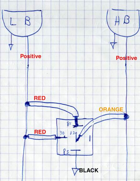
Take a look at the schematic below showing the wiring to pins on the Siemens relay.
Note that most 12 Volt relays have the same pin numbering, though the pin arrangement
isn't always the same. The Siemens relay I used can be wired to be either N/O
or N/C, depending on whether you use pin 87 or 87A. To use this relay in a N/C
configuration, we want to use pin 87A.
 Click
for larger image
Click
for larger image
ABOVE: Schematic showing the wiring to pins on the Siemens relay. NOTE PIN 81
SHOULD READ 86!!
 Click
for larger image
Click
for larger image
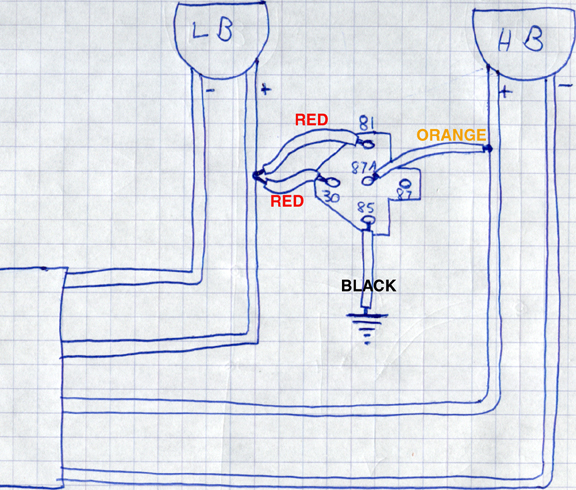
ABOVE: Wiring diagram showing how the relay harness was wired on my passenger's
side headlights. Note how the low beam + positive lead supplies both the power
to energise the relay (switching it to the OPEN position) and also supplies the
power which will flow through to the low beam HID. NOTE PIN 81 SHOULD READ 86!!
 Click
here for larger image
Click
here for larger image
ABOVE: Siemens relay and harness bought from Orvac's electronics www.orvac.com
 Click
here for larger image
Click
here for larger image
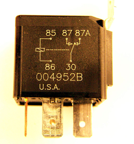
ABOVE: Close up of pin diagram. Note how this relay can be wired either N/C or
N/O. pin 87 is for N/O, and pin 87A is for N/C. We want to use pin 87A for our
N/C arrangement.
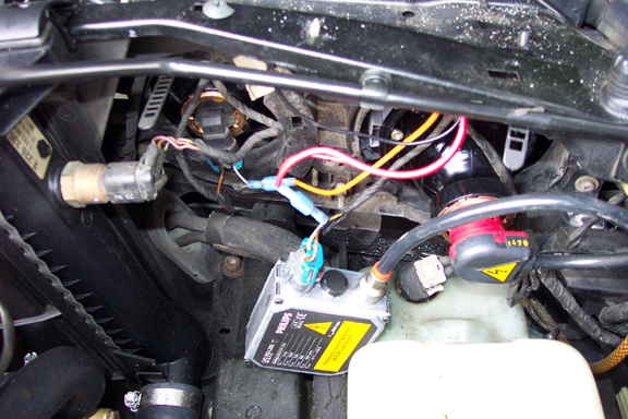
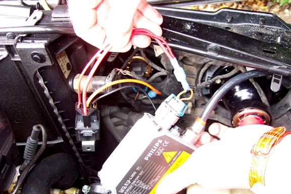
ABOVE: General overview of passenger's side with ballast pulled away. Relay is
mounted under bulkhead.
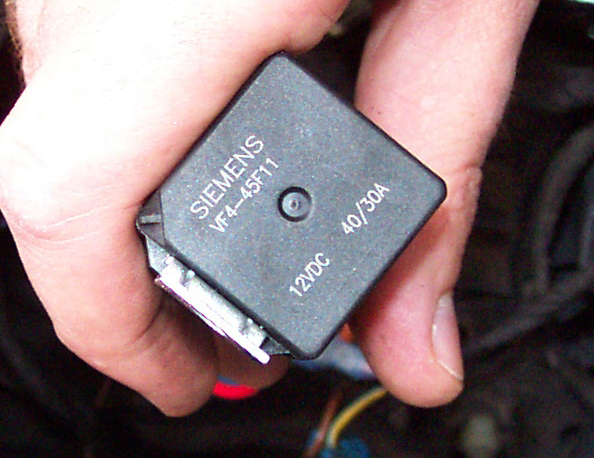
ABOVE:Top view of Siemens relay, including model number VF4-45F11. Vital stats:
12 VDC, 30 amps. A relay with a 15 amp rating would be fine.
 Click for larger
image
Click for larger
image
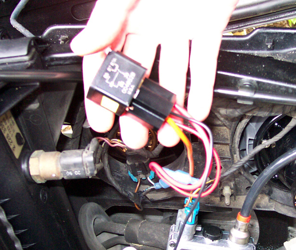
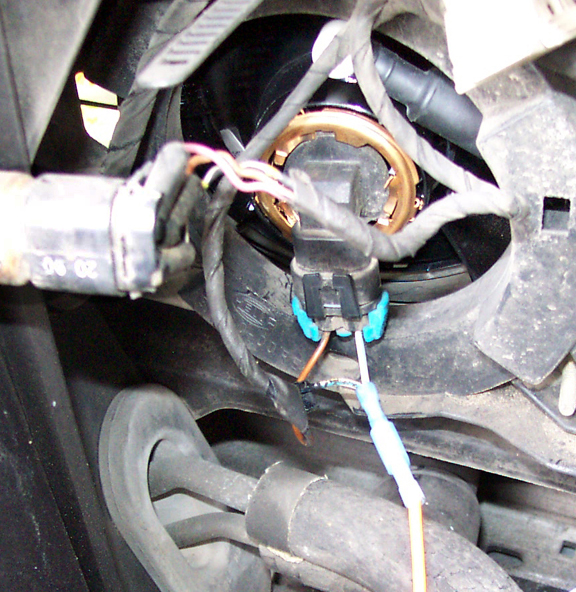
ABOVE: Here you can clearly see the two RED wires from pins 30 and 81 joined with
the low beam + positive lead.
 Click for larger
image
Click for larger
image
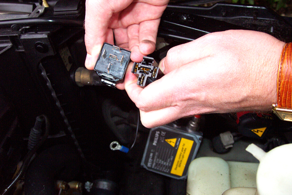
ABOVE: Relay plugged into harness. Below my thumb is the metal mounting tab.
 Click for larger image
ABOVE: The BLACK ground wire from the relay harness will be attached using the
screw and mounting tab of the relay. The same screw mounts the relay and grounds
it to the body as well.
 Click for larger
image
Click for larger
image
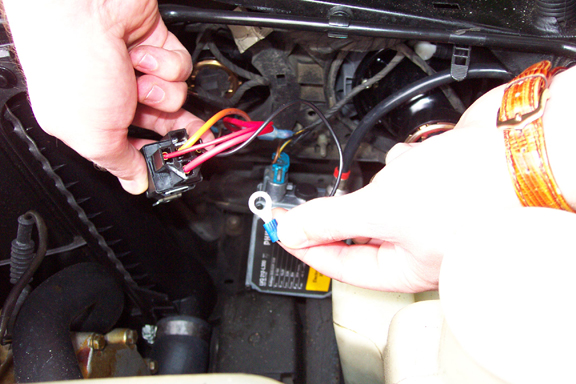
ABOVE: A look at the relay pins and harness plug. Note on the plug how there is
no wire in the top position. This terminal is for using the relay in a N/O (normally
open) configuration. This relay is used in a N/C configuration, so I removed the
BLUE wire from the harness that would have connected to pin 87.
 Click for larger
image
Click for larger
image
ABOVE: Close up of ORANGE wire joined to high beam + positive lead.
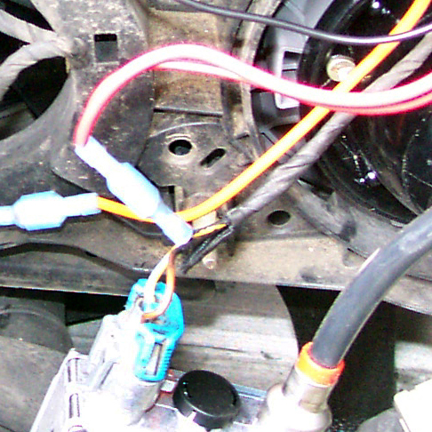
ABOVE: Close up of RED wires joining low beam + positive lead.
 Click
for larger image
Click
for larger image
 Click
for larger image
Click
for larger image
 Click
for larger image
Click
for larger image